
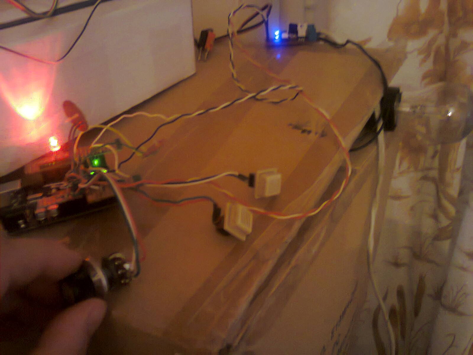
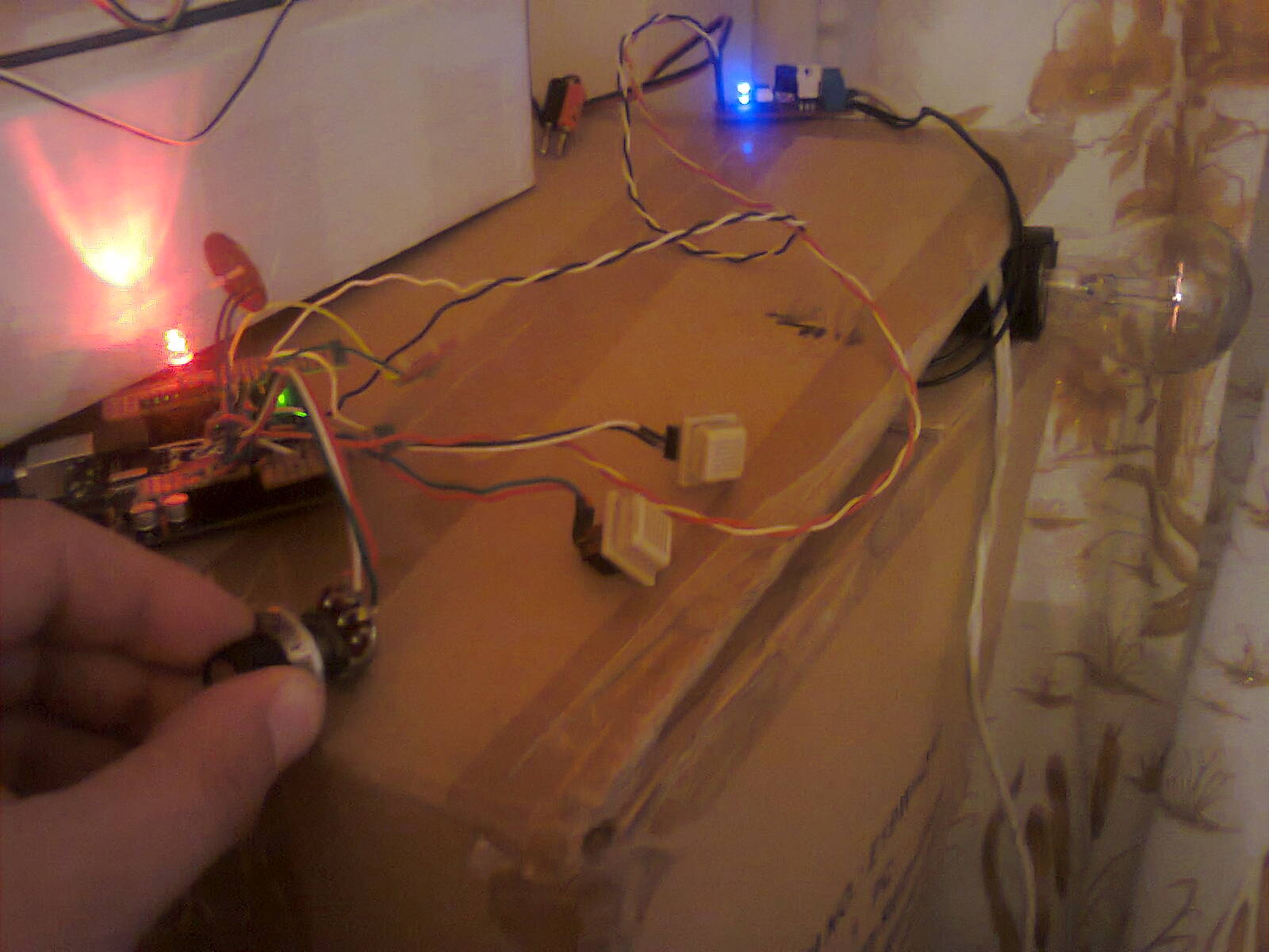
Am revenit la partea de variator de tensiune pentru bec cu incandescenta (adica ac light dimmer) cu documentatia prezentata la DXARTS, de data asta cu controlul intensitatii becului alimentat la retea (230V) cu un potentiometru.

/*
AC Light ControlUpdated by Robert Twomey
Changed zero-crossing detection to look for RISING edge rather
than falling. (originally it was only chopping the negative half
of the AC wave form).Also changed the dim_check() to turn on the Triac, leaving it on
until the zero_cross_detect() turn’s it off.Ryan McLaughlin
The hardware consists of an Triac to act as an A/C switch and
an opto-isolator to give us a zero-crossing reference.
The software uses two interrupts to control dimming of the light.
The first is a hardware interrupt to detect the zero-cross of
the AC sine wave, the second is software based and always running
at 1/128 of the AC wave speed. After the zero-cross is detected
the function check to make sure the proper dimming level has been
reached and the light is turned on mid-wave, only providing
partial current and therefore dimming our AC load.Thanks to http://www.andrewkilpatrick.org/blog/?page_id=445
and http://www.hoelscher-hi.de/hendrik/english/dimmer.htm*/
#include // Avaiable from http://www.arduino.cc/playground/Code/Timer1
volatile int i=0; // Variable to use as a counter
volatile boolean zero_cross=0; // Boolean to store a “switch” to tell us if we have crossed zero
int AC_pin = 3; // Output to Opto Triac
int POT_pin = A3; // Pot for testing the dimming
int LED = 11; // LED for testing
int dim = 0; // Dimming level (0-128) 0 = on, 128 = 0ffint freqStep = 75; // This is the delay-per-brightness step in microseconds.
// It is calculated based on the frequency of your voltage supply (50Hz or 60Hz)
// and the number of brightness steps you want.
//
// The only tricky part is that the chopper circuit chops the AC wave twice per
// cycle, once on the positive half and once at the negative half. This meeans
// the chopping happens at 120Hz for a 60Hz supply or 100Hz for a 50Hz supply.// To calculate freqStep you divide the length of one full half-wave of the power
// cycle (in microseconds) by the number of brightness steps.
//
// (1000000 uS / 120 Hz) / 128 brightness steps = 65 uS / brightness step
//
// 1000000 us / 120 Hz = 8333 uS, length of one half-wave.void setup() { // Begin setup
pinMode(AC_pin, OUTPUT); // Set the Triac pin as output
pinMode(LED, OUTPUT); // Set the LED pin as output
attachInterrupt(0, zero_cross_detect, RISING); // Attach an Interupt to Pin 2 (interupt 0) for Zero Cross Detection
Timer1.initialize(freqStep); // Initialize TimerOne library for the freq we need
Timer1.attachInterrupt(dim_check, freqStep);
// Use the TimerOne Library to attach an interrupt
// to the function we use to check to see if it is
// the right time to fire the triac. This function
// will now run every freqStep in microseconds.
}void zero_cross_detect() {
zero_cross = true; // set the boolean to true to tell our dimming function that a zero cross has occured
i=0;
digitalWrite(AC_pin, LOW);
}// Turn on the TRIAC at the appropriate time
void dim_check() {
if(zero_cross == true) {
if(i>=dim) {
digitalWrite(AC_pin, HIGH); // turn on light
i=0; // reset time step counter
zero_cross=false; // reset zero cross detection
}
else {
i++; // increment time step counter
}
}
}void loop() {
dim = analogRead(POT_pin) / 8; // read dimmer value from potentiometer
analogWrite(LED, dim); // write dimmer value to the LED, for debugging
}


/*
AC Light Control
Updated by Robert Twomey <rtwomey@u.washington.edu>
Ryan McLaughlin <ryanjmclaughlin@gmail.com>
Thanks to http://www.andrewkilpatrick.org/blog/?page_id=445
and http://www.hoelscher-hi.de/hendrik/english/dimmer.htm
modified sketch by niq_ro from http://www.tehnic.go.ro &
http://www.nicuflorica.blogspot.com
version 1m2 – 15.04.2013*/
#include // Avaiable from http://www.arduino.cc/playground/Code/Timer1volatile int i=0; // Variable to use as a counter
volatile boolean zero_cross=0; // Boolean to store a “switch” to tell us if we have crossed zero
int AC_pin = 3; // Output to Opto Triac
int POT_pin = A3; // Pot for testing the dimming
int LED = 10; // LED for testing
int LED2 =11; // second LED
int dim = 0; // Dimming level (0-128) 0 = on, 128 = 0ffint freqStep = 75; // This is the delay-per-brightness step in microseconds (for 50Hz)
void setup() { // Begin setup
pinMode(AC_pin, OUTPUT); // Set the Triac pin as output
pinMode(LED, OUTPUT); // Set the LED pin as output
pinMode(LED2, OUTPUT); // Set the LED2 pin as output
attachInterrupt(0, zero_cross_detect, RISING); // Attach an Interupt to Pin 2 (interupt 0) for Zero Cross Detection
Timer1.initialize(freqStep); // Initialize TimerOne library for the freq we need
Timer1.attachInterrupt(dim_check, freqStep);
// Use the TimerOne Library to attach an interrupt
// to the function we use to check to see if it is
// the right time to fire the triac. This function
// will now run every freqStep in microseconds.
}void zero_cross_detect() {
zero_cross = true; // set the boolean to true to tell our dimming function that a zero cross has occured
i=0;
digitalWrite(AC_pin, LOW);
}// Turn on the TRIAC at the appropriate time
void dim_check() {
if(zero_cross == true) {
if(i>=dim) {
digitalWrite(AC_pin, HIGH); // turn on light
i=0; // reset time step counter
zero_cross=false; // reset zero cross detection
}
else {
i++; // increment time step counter
}
}
}void loop() {
dim = analogRead(POT_pin) / 8; // read dimmer value from potentiometer
analogWrite(LED, dim); // write dimmer value to the LED, for debugging
analogWrite(LED2, 255-2*dim); // write dimmer value to the second LED, for debugging
}
Un filmulet cu functionarea acestui variator de tensiune pentru bec comandat de un potentiometru se numeste ac light dimmer with Arduino (XIV):
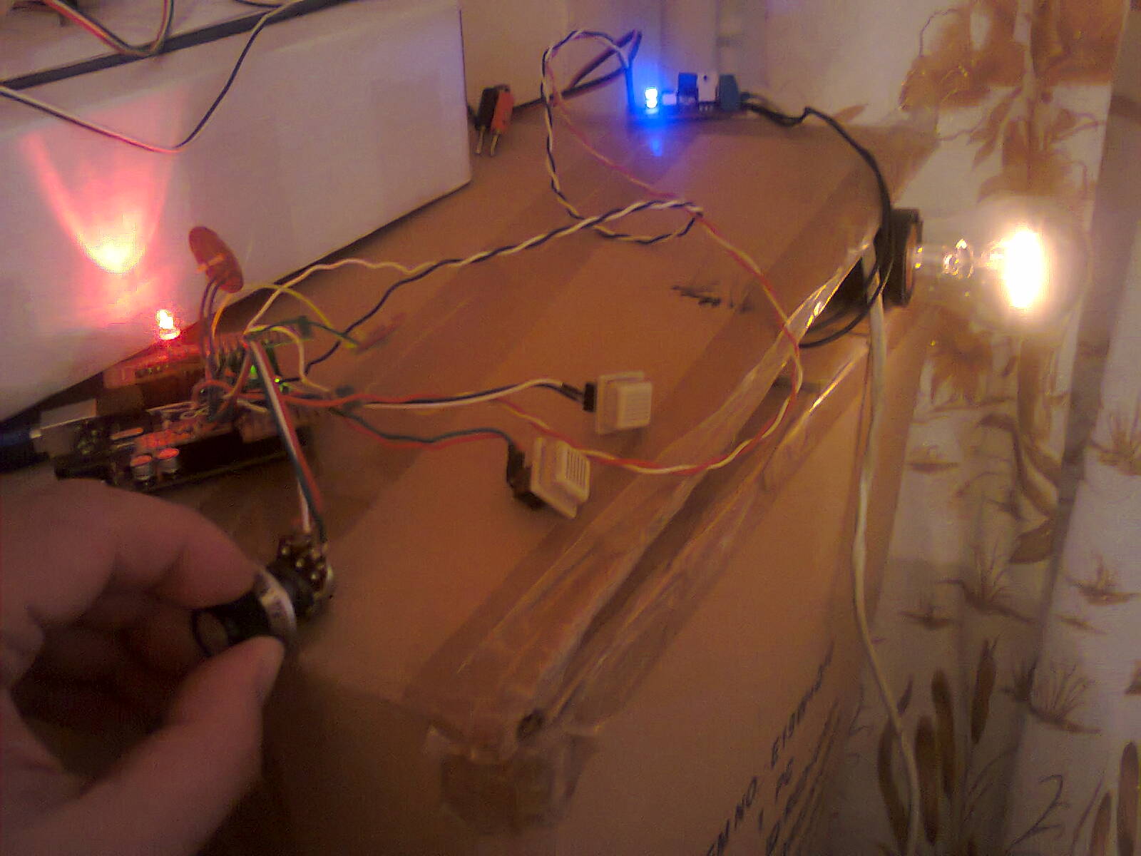
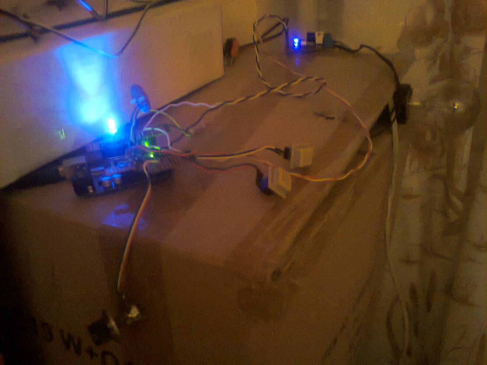
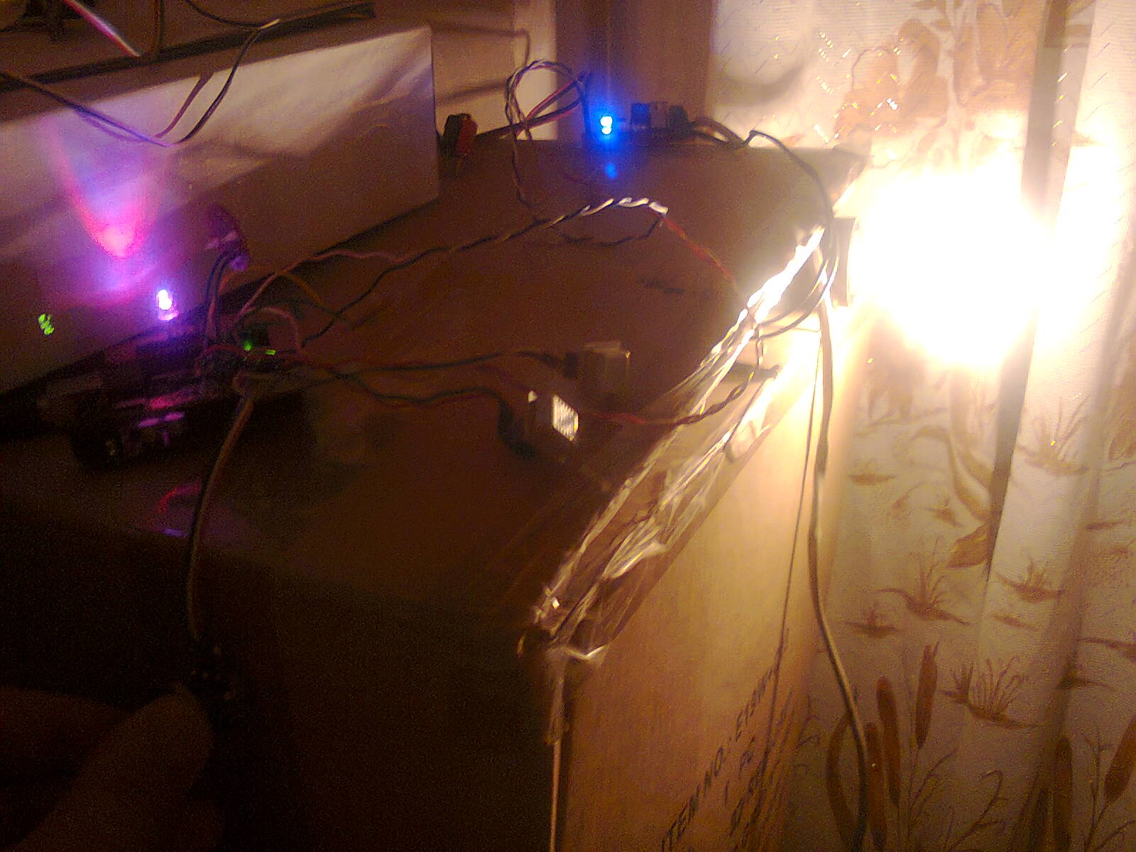
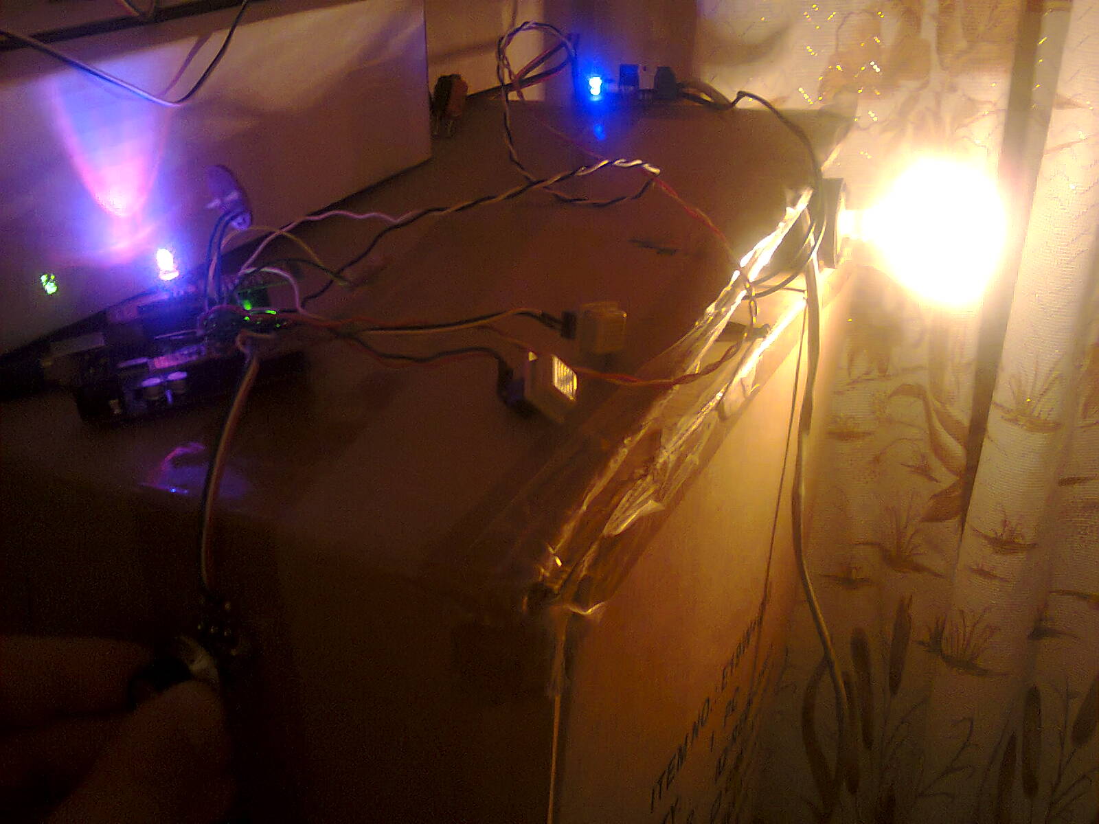
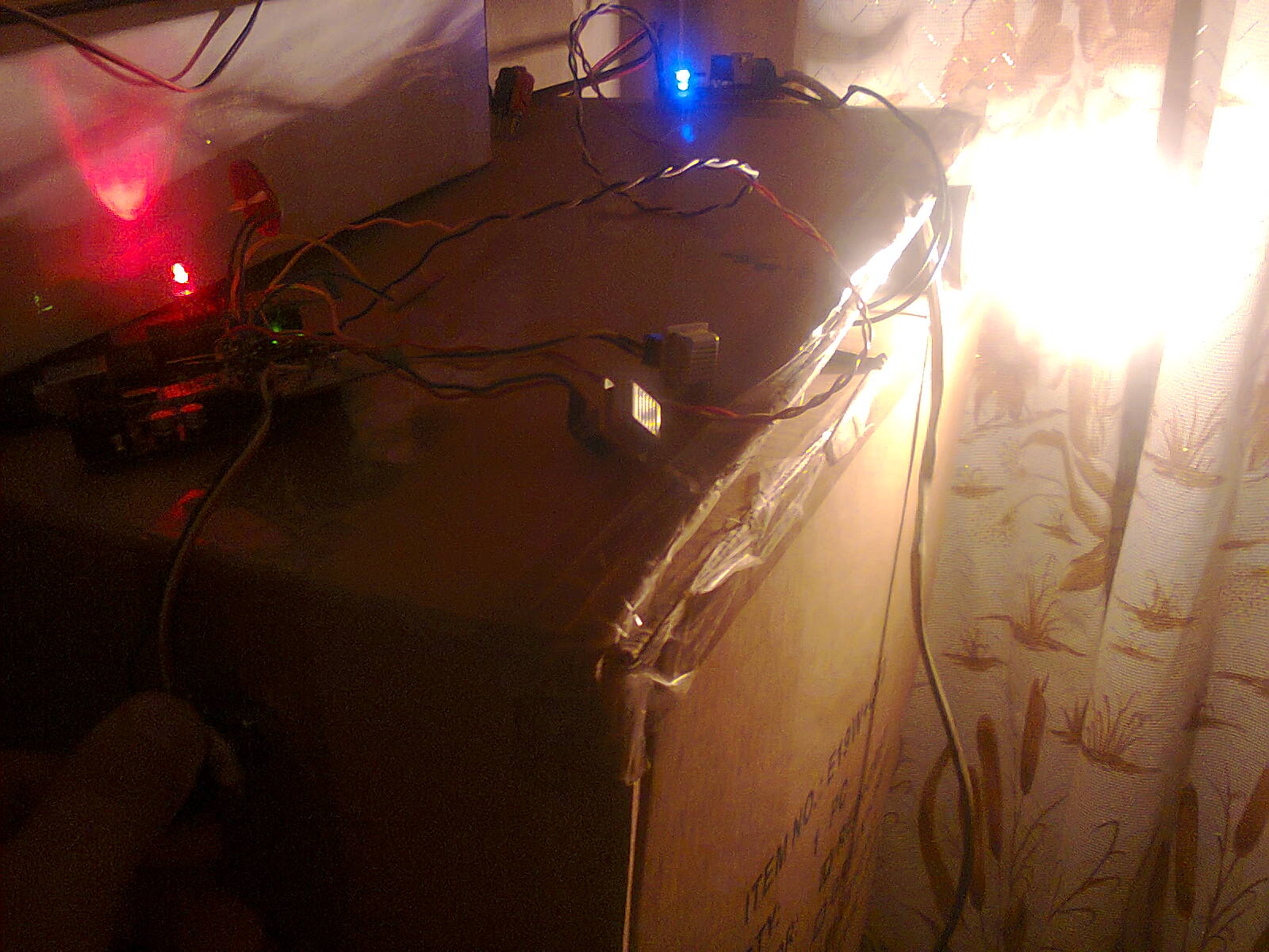
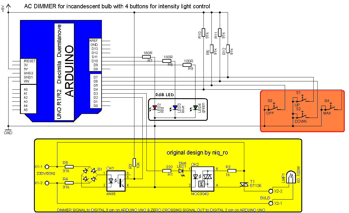
Revenind la partea de butoane, vom folosi 4….
sketch-ul este:
/*
AC Light Control
Updated by Robert Twomey <rtwomey@u.washington.edu>
Thanks to http://www.andrewkilpatrick.org/blog/?page_id=445
and http://www.hoelscher-hi.de/hendrik/english/dimmer.htm
adapted sketch by niq_ro from
http://www.tehnic.go.ro
http://www.niqro.3x.ro
http://nicuflorica.blogspot.com
*/#include <TimerOne.h> // Avaiable from http://www.arduino.cc/playground/Code/Timer1
volatile int i=0; // Variable to use as a counter
volatile boolean zero_cross=0; // Boolean to store a “switch” to tell us if we have crossed zero
int AC_pin = 3; // Output to Opto Triac
int buton1 = 4; // first button at pin 4
int buton2 = 5; // second button at pin 5
int buton3 = 6; // second button at pin 6
int buton4 = 7; // second button at pin 7
int redLED = 11; // red LED at pin 11
int greenLED = 9; // green LED at pin 9
int blueLED = 10; // blue LED at pin 10
int dim2 = 0; // led control
int dim = 128; // Dimming level (0-128) 0 = on, 128 = 0ff
int pas = 8; // step for count;
// version: 4m7 (15.04.2013 – Craiova, Romania) – 16 steps, 4 button & LED blue to red (off to MAX)int freqStep = 75; // This is the delay-per-brightness step in microseconds.
void setup() { // Begin setup
Serial.begin(9600);
pinMode(buton1, INPUT); // set buton1 pin as input
pinMode(AC_pin, OUTPUT); // Set the Triac pin as output
pinMode(redLED, OUTPUT); // Set the LED pin as output
pinMode(greenLED, OUTPUT); // Set the LED pin as output
pinMode(blueLED, OUTPUT); // Set the LED pin as output
attachInterrupt(0, zero_cross_detect, RISING); // Attach an Interupt to Pin 2 (interupt 0) for Zero Cross Detection
Timer1.initialize(freqStep); // Initialize TimerOne library for the freq we need
Timer1.attachInterrupt(dim_check, freqStep);
// Use the TimerOne Library to attach an interrupt
}void zero_cross_detect() {
zero_cross = true; // set the boolean to true to tell our dimming function that a zero cross has occured
i=0;
digitalWrite(AC_pin, LOW);
}// Turn on the TRIAC at the appropriate time
void dim_check() {
if(zero_cross == true) {
if(i>=dim) {
digitalWrite(AC_pin, HIGH); // turn on light
i=0; // reset time step counter
zero_cross=false; // reset zero cross detection
}
else {
i++; // increment time step counter
}
}
}void loop() {
if (digitalRead(buton3) == LOW)
{
dim = 0;
}
if (digitalRead(buton4) == LOW)
{
dim = 127;
}if (digitalRead(buton1) == LOW)
{
if (dim<127)
{
dim = dim + pas;
if (dim>127)
{
dim=127;
}
}
else
{
analogWrite(greenLED, 255); // LED is ON for indicate an error
delay (100);
analogWrite(greenLED, 0); // LED is now OFF
}
}
if (digitalRead(buton2) == LOW)
{
if (dim>5)
{
dim = dim – pas;
if (dim<0)
{
dim=1;
}
}
else
{
analogWrite(greenLED, 255); // LED is ON for indicate an error
delay (100);
analogWrite(greenLED, 0); // LED is now OFF
}
}
while (digitalRead(buton1) == LOW) { }
delay(10); // waiting little bit…
while (digitalRead(buton2) == LOW) { }
delay(10); // waiting little bit…analogWrite(blueLED, 2*dim); // write dimmer value to the LED, for debugging
dim2 = 255-2*dim;
if (dim2<0)
{
dim2 = 0;
}
analogWrite(redLED, dim2); // write dimmer value to the LED, for debuggingSerial.print(“dim=”);
Serial.print(dim);Serial.print(” dim2=”);
Serial.print(dim2);
Serial.print(” dim1=”);
Serial.print(2*dim);
Serial.print(‘\n’);
delay (100);
}
Un filmulet cu functionarea acestui variator de tensiune pentru bec comandat de un potentiometru se numeste ac light dimmer with Arduino (XV):
Sursă: Nicu FLORICA


nu e cam scump sa dimuiesti un bec cu un arduino ?
ba e, da’ am prezentat diverse variante de control, urmeaza prin bluetooth, apoi wireless.. ;-D
Salut Nicu , am ceva probleme cu sketch-ul
” Timer1.initialize(freqStep);
Timer1.attachInterrupt(dim_check, freqStep); ”
Imi apare eroarea : Timer1 nu este declarat
Ceva sfaturi d depanare ?
Multumesc